Page 1 of 2
LED output voltage
Posted: Mon Jan 18, 2021 10:56 pm
by BarryC
Another question; what is the output voltage for the LED Lighting at the "L" connectors on the TK60G2?
TIA,
BArry
Re: LED output voltage
Posted: Mon Jan 18, 2021 11:46 pm
by Jofaur86
Hello,
Personally, I would say that voltage ditto as original HL, since TK intended to replace an RX 18,

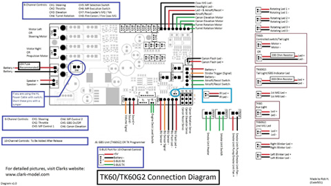
according to the attached diagram, there seems to be an R of 200 homs on L4 and or
connection diagram
http://www.clark-model.com/eng/prod_rx60/index.html

- 881E31F8-7CC9-46DB-9366-88038DD7CB37.png (135.32 KiB) Viewed 4274 times
Re: LED output voltage
Posted: Tue Jan 19, 2021 12:01 am
by BarryC
Thank you sir,
Yep, got all that but I can't find where it references the output of L1-L8.

Is it 3v, 5v, 12v or 5v-12v?
Barry
Re: LED output voltage
Posted: Tue Jan 19, 2021 10:25 am
by Jofaur86
Hello,
I don't understand the reason for your concern

personal for me if replaces an RX? why would the voltage of the led be different, ie 3 volts, that would be indicated, no? do a test with a diode? there is no risk of something on the board toasting, just the led, if there was any voltage? not the right one, just respect the meaning, more, less, otherwise the lighting will not work

Re: LED output voltage
Posted: Tue Jan 19, 2021 11:02 am
by 43rdRecceReg
Barry, The terminals are designed, I expect, to deliver the right amount of juice needed by the LEDs typically found on RC tank models. Given that manufacturers of RTR (HL, Taigen, Tamiya etc) tanks will use specific LEDS for specific tasks, (rear lights, Airsoft warning light, etc.,..) the expected draw will have been catered for in their circuitry and firmware, on that basis. The same will be true of the Clark board, that is, on the basis of substituting a
Clark controller board for the OEM one found in the model.
Resistors would have been fitted inline where needed, in some cases.
I wouldn't worry too much, except that where a specific resistor is recommended for an LED circuit, it would be wise to fit one. I'm guessing this may because some newer aftermarket boards can take up to 12DCV, where many original tank circuits were based on 7.2 to 7.4 DCV originally. My guess for the voltage would be +5v, as this would be found in most circuits.
Incidentally, some of the LEDs listed here, can accept up to 12DCV directly.

If you need something that strong.
https://www.componentshop.co.uk/leds/micro-leds.html
a useful refresher on LEDs (I use it myself

)
https://www.smallscalelights.co.uk/prod ... o-leds-pdf
Re: LED output voltage
Posted: Tue Jan 19, 2021 1:05 pm
by BarryC
I guess I'm asking because I really would like to know. I understand the "science" of LED's and know that they come in different voltage rating.
Given my Abrams will not be using OEM LED's and I will be purchasing specific LED's for specific functions I need to know what LED's from a voltage requirement I should order.
Barry
Re: LED output voltage
Posted: Tue Jan 19, 2021 1:12 pm
by abramsky
Hello Barry
Usually 3 and 5mm LEDs are powered with 2-4V ( depending on their color ). I think this should help you:
https://kithub.cc/2015/11/how-many-volt ... -an-led-2/
And if you want to know the supply voltage in the LED sockets in your Clark MFU - just check each socket with a voltmeter and that's it. The LED supply voltage from the MFU should not change after changing the battery from 2s to 3s or if you are using a battery and the voltage drops. The voltage regulator circuit in the MFU should be responsible for this. Otherwise, the LEDs would glow with different intensity depending on the voltage drop in the battery (e.g. while driving a model less intense when the model is moving, and brighter when you stop).
Re: LED output voltage
Posted: Tue Jan 19, 2021 1:31 pm
by BarryC
Thanks Abramsky,
The link will come in handy.

Checking with a meter was my next step. I just thought someone here would have the answer.

Barry
Re: LED output voltage
Posted: Tue Jan 19, 2021 1:54 pm
by abramsky
You're welcome. Just don't take measurements directly at the LED sockets. Since there is not much room there - the voltmeter probes can cause an accidental short circuit (touch each other). The best way is to use the same cable with the JST plug as you will next use with LED's. And don't forget to protect the free cable ends against short circuits using e.g. insulated test clamps.
Good luck

Re: LED output voltage
Posted: Tue Jan 19, 2021 2:09 pm
by 43rdRecceReg
BarryC wrote:Thanks Abramsky,
The link will come in handy.

Checking with a meter was my next step. I just thought someone here would have the answer.

Barry
That's handy chart from Abramsky. I said +5v because most of the circuits use it, but then these are attenuated for specific needs (gun, elevation motors etc) by the firmware and regulators. Most model LEDS go from 1.2 up to 3V (depending on colour as in Abramsky's handy chart), but it's not the voltage that fries LEDs, it's the current (Amps/mA).
This will be set at an acceptable level by the board for the components. This is where multimeters come in handy.

Yuo can always test LEDs before using them with a breadboard and a battery pack DC supply. That's what i do.

Edit: once the output is known, it's easy to calculate resistors needed (if they're needed) for specifically rated of LEDs. This site is very useful for that.
https://www.petervis.com/electronics/le ... lator.html
Good luck, Barry. and looking forward to seeing the latest Meisterwerke!

